Blaster Assistance Requested: EE-3 / MPP Flash "Mystery Holes" Alignment

JGattonII

New Hunter
Hi All!

While trying to wrap-up a few odds and ends for my EE-3 build, I realized that I had not yet dilled the "mystery holes" into the end of my MPP and so I began researching their precise placement.

Disclaimer: I must first admit that I'm not very educated in - and/or experienced with - the proper methods for determining these types of things but that doesn't stop me from attempting to muddle my way through based upon general logic/reasoning. If anyone has advice, pointers and/or know of any learning resources (preferably reasonably priced) for this type of thing then I would be very interested in picking-up some skills in 'photogrammetry' and such.; I think that's the right term anyways?!?

At any rate, I found the photo below from within a post made by The5thHorseman in an earlier thread ....

MPP_Holes.jpg


...but the "Mystery Holes'" misalignment pushed me to do some further investigation.

EE-3_MPP_Highlight2.png


As it turns out, however, my (uneducated/inexperienced; see disclaimer above) calculations seem to point to an even greater misalignment, as-in perhaps 8 degrees of difference?!? Perhaps someone w/ more experience might examine the pictures below and help me understand where my logic would be flawed? Note that the full original photo is also included for reference.

EE-3_MPP_MH_Measurements.png


Based upon this reference photo posted by Art Andrews :
Boba-Fett-Costume-Empire-Strikes-Back-Hallway-07.jpg
 
After receiving 93 reviews on this thread - and no replies - I actually found something very unexpected... Encouragement! I mean, if I was totally out of my mind then someone would've surely called me out by now, right? At any rate, I decided to dig into it a little further and I'm honestly now even more assured of my earlier findings.

I began by locating a seemingly accurate MPP template and used it to design a 3D version in Autodesk Fusion 360. After aligning the MPP to the imported picture as best I could, I projected the approximate size/location of the mystery holes onto the curved surface of the flash tube and then extruded the profiles to create my mystery holes.

MPP_MysteryHoles2.png


MPP_MysteryHoles1.png


MPP_MysteryHoles3.png


Afterwards, I flattened the tube so that I could begin taking measurements.

MPP_MysteryHoles4.png


I'll say this: if I'm crazy, I'm at least consistent.

Center points show 8.2 degrees of deviation.

MPP_MysteryHoles5.png
 
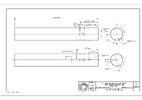
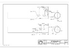
I don't know if you saw this in my 3D projects thread (RafalFett's Boba Fett 3D Projects), but I used photos posted by Fettastic and compiled by me to add all the holes to my model, but I also used this template made by Seven:
Thank you RafalFett!! I was totally unaware of those drawings and hadn't even considered using your model in the simulation. I really like that idea though so will re-run the gauntlet w/ them instead and report back w/ my findings.
 
JGattonII

Keep it up. The method you are using to figure out the alignment is basically what I did about 20 years ago to get the dimensions for the ESB flame thrower, gauntlet darts (before they were discovered) and the gauntlet rocket. Those ancient threads were started on the As You Wish forum.

ESB gauntlets,.... let's make 'em accurate

 
Dang that’s before a lot of our time!

I know there’s a lot of variances with hole sizes and placement when it comes to MPPs…I wonder if this has any variance to it as well.
 
Keep it up. The method you are using to figure out the alignment is basically what I did about 20 years ago to get the dimensions for the ESB flame thrower, gauntlet darts (before they were discovered) and the gauntlet rocket. Those ancient threads were started on the As You Wish forum.
Thank you very much Boba Phett. That is very encouraging to hear! I will certainly keep running with it until I find a solution or determine that one doesn't exist within grasp of my mind- and/or tool-set.

I know there’s a lot of variances with hole sizes and placement when it comes to MPPs…I wonder if this has any variance to it as well.
To be honest, that's one of my biggest hurdles right now. Every scenario I've run thus far has me convinced that the holes are staggered but the question I'm still struggling to answer is: "but just staggered are they?" Getting to that answer requires me to use 3D MPP models that I (and now also using those from RafalFett) have designed based upon dimensions, drawings and/or pictures of various users' MPP's - and then scaling those to Boba's MPP in order to calculate the various measurements. If MPP's themselves vary as much as the designs/templates I've run across even thus far, then it may be close to impossible to calculate with a high degree of certainty (at least based upon the current method I'm utilizing). Just as an example, based upon my most recent run-through, a 1.5mm change to where the holes start from the end of the tube (i.e. scaling Boba's down to the same distance as Rafalfett's version) makes the differential between the holes shift from 8 degrees to 10! Needless to say, I have more work to do before even forming my own opinion on it - much less putting it out there for others to consider as being a remote possibility.
 
Personally im of the opinion that they are more or less in line with one another. My theory on them is that the flash was possibly taken from a failed or extra Stunt Vader saber, where small set screws were possibly drilled and tapped into the steel mpp shroud and through the tube in order to hold the stunt blade in. It is possible they didn't do it perfect. It's all theory though
Regarding your drawing overlays, I can see some small deviation in your scaling and angular orientation of the model/picture overlays, including the mystery hole sizes themselves being a little too small on your model atm
 
Last edited:
Thank you very much for the insight and constructive criticism ConvergenceProp. Your builds exude a heightened (perhaps almost like 'enlightened') attention to detail and so I sincerely appreciate your comments, respect your stance and welcome any/all attempts to help me develop and sharpen my skills in this arena.

Overall, I can definitely see where the general intention was to drill the holes inline with one another. Based upon that fact alone, this whole venture could be perceived as superfluous by some - but yet I still find myself intrigued. I could also totally buy-in to the stunt saber theory for why they are there in the first place.

As for the scaling, angles and orientation of the drawings overlaying the photos, you are 100% correct that there are deviations between them. Although Im sure that a lot of it could be due to the limitations of my skillset, experience, etc., the weakest link at this point is in my assurance of my MPP design's conformity to an actual part. For example, the only benchmark I have for the MPP tube's metal thickness is 2mm thick. When trying to align off of holes' dimensions from both an interior and exterior profile perspective means that the material thickness becomes an important factor. For the life of me I can't make a 2mm thick tube with holes placed as measured fit to photo constraints.

Short of an actual MPP in-hand, what I would really love is to have someone provide a digital caliper reading of actual MPP's material thickness and diameter - as well as a scanned old-school-style pencil-rubbing on paper of an actual MPP's port holes and engraving. My design program could then take that flat pattern and roll it up to the appropriate tube dimensions - and extrude the profile to the appropriate thickness. Any chance you (or someone else) may be willing to help with that??? =)
 
Last edited:
FWIW, I did want to address the hole size discrepancy pointed out in the abbreviated excerpt below:

I can see some small deviation in ... the mystery hole sizes themselves being a little too small on your model atm

While it may not be a best-practice solution, under-sizing the holes was an intentional decision while still in 'measurement mode.' I originally began by looking at the holes' exterior profiles as the basis for determining alignment; see first pics posted where basing it off of angles alone. After finding that the photo quality made it rather subjective to judge where they end, however, I chose to move towards a more center-point-based measurement solution. As such, I created a quasi point-cloud based upon the perceived edge for each hole to find the center - and then measured out a 2mm hole from that so that I could still see all photo edges while still aligning the two. In retrospect, I should've explicitly stated all of that and so apologize for the confusion.
 
Last edited:
This thread is more than 2 years old.

Your message may be considered spam for the following reasons:

  1. This thread hasn't been active in some time. A new post in this thread might not contribute constructively to this discussion after so long.
If you wish to reply despite these issues, check the box below before replying.
Be aware that malicious compliance may result in more severe penalties.
Back
Top