I have decided to upload pics of the build along with build diary/instructions. First is a list of the letters I use for assessment. Enjoy if you’re on a quest for a budget blaster banger!
C = CUT
D = DETACH
F = FABRICATE
M = MODIFY
N = NOT NEEDED
R = REMOVE
T = TRIM
U = UNDO
This is the original Blaster pics on which I have identified what needs doing.
PIC 1. Need to cut off the scope rear, middle and front sections and discard. (I have a real scope to replace this with).
Need to: modify the top lug on back of grip frame, remove bottom lug on back of grip frame, modify the scope mounts, fill screw holes and modify right side grip and modify stock.
Need to remove stock to frame bracket and replace with modified version
Need to trim, fill and shape some items as the build gets on.
Here we go then, let’s make a start.
PIC 2. Scope parts cut off and discarded, then undo 2 pistol grip screws, ease grip frame apart and detach mounting bracket with stock. Side to side whilst pulling should do the trick. The T marks areas that need trimming, as shown, later.
PIC 3. Undue and remove 6 screws from right hand side of stock and 2 screws, from left side of stock to frame mounting bracket. (Save screws as they are needed for later in build).
Separate stock as shown by wibbling (technical word) a knife or screwdriver in the joining seam. Mine was not glued so should be OK. Although the mounting bracket is to be replaced in this build, keep it for use as a template later.
PIC 4. My unbranded old 4X20 scope that closely matches.
PIC 5. Scope stripped down. I discard mounts to my save pot as not needed.
The following 4 pics show that I have already modified the scope mounts but forgot to take pics. Never mind, here’s how anyway.
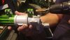
PIC 6. I don’t have a post drill or lathe, so achieved this mod, freehand. I used a 16mm spade, paddle or flat bit, (depending on your local dialect) to drill out and make the mounts bigger. Be careful, not too fast or it will melt. You might want to tape the 2 halves of the mount together if you got a post drill or lathe, I left that out as I wanted it to flex a bit whilst drilling it.
PIC 7. This is a conical drill bit that I used to help with de-burring the mount. Again, watch your speed.
PIC8. Finally, I used a wire brush cup to sand & smooth it, internally. Speed is a factor here. High speed for a few seconds then l
let mount cool. Alternate 'til you’re happy.
PIC 9. After drilling, I then used an exacto type knife to trim the mounts as you can see.
PIC 10. As you can see I think this looks amazing. Almost 100% spot on. At this point I unscrewed the front of scope off and cut scope tube off at front mount. You do lose the fine internal thread of the scope tube but grind down the thread on front scope piece and it will make a nice tight fit. Then remove the rear piece of the scope and cut this, NOT the scope tube, and then superglue it back onto the lock ring as, again, you will lose internal thread on the rear piece. You can look at the later pics to see how this looks. No points for identifying background clutter or for the facts i stuck my thumbe with thr drill, hence the blood under my nail.
PIC 11. I used a brand new very sharp chisel to remove the mounting lug on the lower rear part of the grip frame
PIC 12. I then used a modeller’s fine file to finish it off. I will use sand paper and wet n dry when filled later.
PIC 13. You need to remove all of the excess moulding (arrowed) on side of grip frame down to the level of the top rear lug as shown inset. Do NOT cut/sand down to level of grip frame marked by the X. This mod will assist in the siting of the new mounting bracket.
PIC 14. Using a flat file helps with keeping and checking it is flat and level.
PIC 15. The top rear grip frame lug needs to be as square as you can make it. Take care as this, for me, was a rewarding mod. You will also need to remove the rounded excess underneath the lug. Refer to PIC 2, 27, 28 & 29 for assistive clarity on what needs to be achieved.
The following templates and spacer plates were made from 4mm clear acrylic sheet. Good for marking where holes need to be as it’s clear. Forgot to take pics of this part of the build. Drawn some diagrams instead. Use pics and your own judgement in this part.
PIC 16. Take the original stock to grip frame mounting bracket and the pistol grip to make a template like this. Don’t forget the 4 holes and u shaped cut outs. Try drawing the bottom detail first and then move the piece up, level with the top lug, so that you can follow the bracket top curve. Drawings aren’t great but you get the idea.
PIC 17. Take the original stock to grip frame mounting bracket and turn it over. Now cut and trim out the shaped part that looks like a horseshoe bracket and arm, that fits into the side of the stock. Just cut this arm straight and trim around the greeblie. Get template 1 and lay it down flat. Place a new piece of 4mm acrylic sheet on top of template 1 and place new piece cut from original bracket and place on top of both, greebvlie face up. Now carefully trace out the shape of the bracket and template 1, don't trace around greeblie, stop and continue trace after. Join lines together on template 2 after removing bracket. Keep the bottom of template 1 and the bracket perfectly aligned and you should end up with a drawing on the 4mm acrylic sheet like template 2. This will need to be cut out and sanded and shaped to fit exactly on top of template 1. Always sand and shape them together as one.
PIC 18. If all has gone well, you should have 2 templates that fit together and are shaped like this. Sorry about image size but it was the best i could find
PIC 19. Take the original stock to grip frame mounting bracket and cut out the stock ‘greeblie’ for later use. Make sure there is a piece, of the mounting bracket, left over big enough to cut out the shape in PIC 22. Plaster on my finger is a chisel wound!!
PIC 20. The cut out greeblie. It is a bit thick at this point and will need cutting, shaving and sanding thinner to put back on the stock.
PIC 21. You need to cut out a shape from the mounting bracket excess material.
PIC 22. This is the shape of the piece required. Use the other pics for reference and take measurements from the actual pistol frame
PIC 23, 24, 25 & 26. Score a cut into the plastic and then angle your blade to cut at 45 degrees. This will allow the piece to fold in on itself to form a corner shown in
PIC 26.
PIC 27, 28 & 29. These pics show how this piece needs to be placed and super glued.
PIC 30. This pic shows how the lug should look after sanding and scoring. It is a representation of the welded bracket that comes off the main bracket to grip the side of the pistol frame. It may need deeper outline scoring to get the full effect. I won’t know until primer coat has been done.
THE STOCK MODIFICATION
IMPORTANT Remember to drill a big enough hole for you screw to just pass through each acrylic. A smaller pilot hole should be drilled into the receiving acrylic.
HIGH RISK OF CRACKING THE ACRYLIC IF YOU IGNORE THIS. (Check your medium, if using other materials)
PIC 31. This is the mod to the stock and how it is assembled with the 2 X 4mm templates and 3 additional 4mm acrylic spacing plates. Spacer Plate 1 is screwed (6 screws) to the left stock trapping and holding Template 2 in position. Spacer Plate 2 is screwed (4 screws) to Spacer Plate 1 and Spacer plate 3 is sandwiched between Spacer plate 2 and right stock. This is secured in place by being screwed (6 screws) into position by the screws passing from the right side of stock in its existing holes and secured to Spacer plate 2. Template 1 screws to Spacer Plate 1, with 2 screws, fromthe left side of it and 3 screws through pistol grip, from the right side. Template 2 is screwed to template 1, with one screw through all spacer plates and to the left side of pistol grip throught tempate 1, with one screw in middle of the diamond on grip pattern.
PIC 32. Take the left stock piece and place template 2 into it. Hopefully the holes that you marked and drilled along with the 2 u shaped cut outs should make a nice tight fit. Do not screw in place yet.
PIC 33. Now take one of the 4mm spacer plates and place over this. Mark and drill all screw posts and locating posts. Six screws will eventually hold this plate on and keep template 1 in place. You may need to countersink the screw holes for additional spacer plates. If you are using flathead wood screws or dome head self tappers don’t countersink too deep. We will accommodate the screw heads in another way. There are some annoying little location tabs on the inside of the stock. Break them off.
PIC 34. Take another 4mm spacer plate, depicted in blue, and mark, drill and countersink 4 holes to secure this plate to the first. Remember to drill 4 pilot holes in plate 1 too. If any of pate 1 screw heads are stopping a flat fit then mark them and turn plate 2 over and countersink them to make room. Look at diagram. Red is first plate and blue is second plate with countersinks drilled to accommodate screw head.
PIC 35. Take the right hand stock and a final 4mm spacer plate and offer it to the stock, marking and drilling the main six existing screw holes in stock, remembering to offer stock and plate 3 onto plate 2 to mark pilot holes in plate 2. Remember, right stock and plate 3 are anchored to plate 2. Mark and drill other location posts. Break off those little location tabs.
PIC 36. Now that the stock prep work is done, it’s time to assemble and shape it. Put the 2 templates to one side as not needed for this bit. Using 6 screws, attach spacer plate 1 to the left stock. Using 4 screws, attach spacer plate 2 to spacer plate 1. Screw 6 screws in the existing screw holes on outside of right stock, through spacer plate 3 and into spacer plate 2.
Viola! You should now have a stock that is now an extra 12mm wide by way of the 3x4mm spacer plates.
PIC 37. We are now going to cut off excess spacer plates and shape the stock. Please note that the right side stock is longer at the front than the left. No worries, we are cutting this extra length off. Cut off the spacer plates and right front stock as close to the curve as possible and then cut along top of stock and gently curve the shape out to the rear so that you have a ‘fin’ shape, do same along bottom of stock. Now take it all apart and re-assemble with, this time, template 1 in situ. Once it is all back together. You can now place template 2 onto the left side and it should fit nice and snug into that long gap on the stock. Mark and drill 2 holes to attach to template 1. Don’t forget pilot holes in template 1 as you don’t want to crack it at this stage. Remember to countersink if screw heads are not flush. This diagram is not to scale or shape, it's just to show what to end up with. Look at last picks to see shaping i achieved.
PIC 38. On the right side of pistol grip, remove the 2 screws and drill the holes all the way out the other side. Add an additional hole at the top. Now align template 1 to the pistol grip. A bit fiddly, I know, as it has the stock attached to it as well. Mark the 3 holes on the template 1. Lay template 2 on this and mark the 3 holes. Now drill 3 pilot holes, for the size of screws you have, and screw the pistol frame to template 1. The 3 screws need to be long enough to stick out about 2mm proud of template 1. Drill the 3 holes in template 2 just deep enough for the 2mm excess to fit. This will help stop any pivot action. Finally lay template 2 back in position and screw through template 2 & 1 into pistol grip and again 1 screw through into stock template and spacer plates. And finally, sand, cut and trim all excess plastic on back of greeblie and glue it back in place which will cover up the screw.
YEEAARGHH! ALL MODS COMPLETE
Just the filling, sanding and painting to complete.
PIC 39&40. This is where I am at, at the moment. Basic filling and sanding done. Going to apply first coat of primer next to show up the imperfections.
PIC 41&42. If the truth be known, this is second and third primer coat after imperfections? Erm…. That’s being polite to me, myself and I. More filler, more grinding, more emery grit, more sanding, more wet n dry,
MORE COFFEE OUT HERE WOMAN, I’M DYIN’.
She shouts back.
What did your last servant die of?
I shouted back,
NOT DOING AS THEY WERE TOLD!!!
Within 5 minutes a coffee arrived along with me being told the bedroom trampoline is out of action for a week. Oh well, some you win, some you lose.
That’s it, ‘til the top coat and weathering is done.
P.S. Here's a few pics to show my detailing and weathering skills. I hope i can do this blaster some justice.


 PIC 43 & 44.
 I have now applied 2 coats of dark grey made fromy Tamiya 10ml Matt Black acrylic (XF1) and 5ml German Grey acrylic (XF63)
PIC 45 & 46. More or less finished the paint job. Will add some rust and old age weathering later.
I think this has turned out rather well for my first attempt at this sort of thing, Kid you, I do not.
I have not found any other pics yet, of any Hasbro mods that have gone to the effort of modding and replacing the stock to pistol mounting bracket to the correct style. I am rather proud of that and going to the trouble of widening and reshaping the stock.
I have left the electonics working and not covered up the slots in barrel guard.
Later mods will be lengthning stock and barrel. Cover open slits and re-work T rails. Fill in all screw holes and put correct type of screww heads where they are supposed to be. Cut and re-work battery compartment door to be held in place with magnets. Re- align pistol grip and mounting bracket so it follows contour of grip. Don't know how I got that crooked when I marked and drilled it.
What do you think troopers, any good? Please comment. Thanks.