MachineCraft
Active Hunter
(I know, I know - today is April 1st. This is not an April Fools day joke)
Hi everyone,
I have been anxious to write this post for some time. This is by and large the most complex and time-intensive project we have ever worked on - Definitive Metal Ears for Lineage Helmets.
Backstory:
In late 2021, we started working with new suppliers and gained access to significantly nicer quality parts at better prices - a huge win-win. We had completed our helmet run in 2020 and had run out of ears later that year, but even after the helmet runs we still received many requests for ears sets, including from studios working on The Mandalorian and The Book of Boba Fett. Now that we had access to better suppliers, we knew we could make even nicer ears for less than half of the cost of our original run, and we could pass those savings onto our customers - everybody wins.
The original plan was to use the same models as our original Helmet/Ears run. The raw models were designed by another member of this forum and then scaled and modified in-house for proper fitment on Gen 2+ helmets. These models were worlds better than anything to date as some measurements were taken directly from the real props. In early 2022 we pulled the original models into a CAD program we now use and started to discuss the project with a new production partner.
When we brought the original models back into the design space and started comparing to references, our production partner started pointing out several details that weren't captured in the original models. Some of these flaws are small, and some of them are difficult to be unseen once you know they exist. I was a little caught off guard - I didn't think the original models left much room for improvement. Nonetheless, we discussed further and decided to send the original models out for quotes to ballpark pricing so that we could open up pre-orders and gauge demand while developing an improved set of models using known measurements and reference photos. Our production partner took point on the redesign as he is incredibly talented and has great tools to work around lens distortion when modeling from photographs. Our projected ship date was June/July, 2022.
Improved Models:
In early June 2022, we received improved models for the Left and Lower-Right Ears. The models included features that were missing from the original models and were definitely a step in the right direction. We 3D printed the models with our high resolution SLA printer and things just didn't quite line up the way that we thought they would. Some dimensions lined up perfectly, and others were just off-the-mark. We came to the conclusion that the models we received were already scaled, so we printed them at full scale. Same story - dimensions that did not line up with the first prints were much closer, but the shift caused other things to drift off. This wasn't exactly new to us - we had a similar experience when scaling the original models from our helmet run.
With production well out of reach a week into June , we knew we had to bring in more hard data to use as a 'source of truth' to nail these parts. We got ahold of just that, and started comparing the improved models to the new data in hopes of making minor adjustments to take us right into production. We unfortunately had to part ways with our production partner after acquiring this data, and because the newer models weren't produced in the same CAD software we use, it was easier to just start over from scratch using the new reference.
Final Models:
Here we are - back at square one. I won't lie, this was a pretty low point for myself mentally. While we now had everything we need to produce the best ears possible, nothing up to this point had worked out the way it was supposed to, and we were now well past our projected delivery dates. A plan was developed and we started moving forward.
Step 1 - Model Singular-Interfacing Parts at Full Scale (Left and Lower-Right Ears)
We decided to start by modeling the Left Ear and Lower-Right Ear. Why? Two reasons.
Reason 1) Both of these pieces only directly interface with 1 other part; The Helmet. The less mechanical complexity, the better.
Reason 2) The Left Ear is the largest part of the entire kit that interfaces with the helmet. This also means it will be most affected by even small scaling adjustments. More on scaling later.
Accurately modeling parts you don't physically have in hand is challenging. I used to think that the more types of reference you have, the easier the modelling process becomes. The opposite is true. When working with caliper data, you have to identify which measurements can be relied on, and which to throw out. When working with photos, you have to account for off-axis angles and lens distrotion. When working with 3D data, you have to align mesh models to the planes that you're creating your models on, and/or then to the models themselves - VERY meticulous. Now combine all of these together and you have to create somewhat of tiering system for what data to rely on for whatever feature or dimension you are working on. On top of that, combining all of the data streams rarely leaves you with a nice 1-2 decimal point number, so there is a heavy amount of reverse engineering needed to uncover what dimensions are actually supposed to be.
Initial modeling was a slog for all of the reasons above. While working on the Lower-Right Ear I had a huge "Ah-HA!" moment that turned into developing a workflow I call the "Planes" method. This new method helped me extract really accurate measurements very quickly. I won't bore you with the details, but it was a game changer in this project. I worked through both models at a steady pace until they were complete, and then it was time to begin scaling.
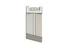
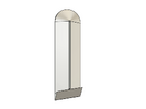
Step 2 - Scaling the Left and Lower-Right Ears
Any time I mention scaling to accuracy-centric people in the community, it seems to be controversial. I totally get that we [collectively] want things to be exactly the same size as the original parts. Consider this: Lets pretend you had two painted Gen 2-3 helmets with say ~1.5% of shrinkage from the original prop; One you install 100% scale ears on, and the other you install ears scaled exactly to the amount of shrinkage the helmets themselves incurred. Now lets pretend that you have to pick these 2 helmets out of a lineup of 10 clones of the original prop. No one is going to pick out the helmet with the scaled ears - we simply cannot see that small of difference without the use of tools. The helmet with full scale ears with the left ear hanging way over the top and bottom of the left ear platform, however, would be easy to spot. All this to say - I promise, you do not want intentionally unscaled ears on an unintentionally scaled helmet.
To begin the scaling process, we started by 3D printing out the ears models at 100% scale using our high-resolution SLA printer. This printer has reliably produced prints for us with around .01-.02mm deviance from specified dimensions, which is remarkable. Once prints of the ears were cured, we affixed them to the helmet with some painters tape, approximated the needed scale, applied that scaling percentage to the full scale models, and began new prints. We repeated this process many times until we found the perfect fit, eventually implementing printd cylindrical studs on the back of both ears to simulate where the mounting hardware passes through the helmet. Now that we had our ideal scaling integer, it was time for the real fun to begin - the Upper-Right Ear assembly.
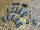
Pictured below: 3D prints of the many iterations we went through during scaling.
Step 3 - Model the Upper-Right Ear Assembly (And a discovery!)
"This is where the fun begins."
When modeling the Upper-Right Ear, you have several things working against you. The Earcap has to mate to the Inner Ear. The Microswitch has to fit in the pocket of the Inner Ear AND has to be properly placed for the Stalk to activate it in the down position. You cannot scale the Microswitch because it is a found part, but it's fit in the original prop is SO tight that making any modification can and will cause interferance. The Axle Screw has to pass through the Inner Ear, through the Stalk, and into the Earcap with such tight fit that it keeps tension on the Stalk without overtightening. The wiring exit from the Stalk needs to line up with the radius slot of the Inner Ear to allow wires to pass through and into the helmet from the Rangefinder. On top of all this, the assembly as a whole has to both look the part and clear the Lower-Right Ear if used on an ESB helmet. This assembly was a lot of work. It is also the part of the kit that is most different from our original "Hero Ears" run. I was never 100% satisfied with how this assembly fit the helmets on our original run, but chalked it up to the outright wonkiness of the ESB helmet; The real reason would actually be discovered next.
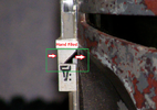
We started with the Earcap using the same methods we did on the previous pieces. To my surprise, the Earcap actually ended up being one of the smoothest pieces to model - until I got to the large feature on the bottom-center (Side Note: Do we have a name for this thing?). This feature was not lining up well, but everything else was, ruling out needing to align the part to the reference better. It was at that moment that I remembered a detail that boba87fett incorporated into their Elstree Precision ears, originally pointed out to him by Cantina Dude - the oddly rounded inside corner. After some studying the newer data and looking at reference photos, a discovery was made. The corner in question isn't rounded because of a broken or rounded end mill that was used to machine them, the corner is rounded because the right side of that bottom-center feature was HEAVILY filed down to clear the Lower-Right Ear! For ESB/SE Helmets, the bottom-center Earcap feature should NOT be centered and should be biased toward the left side if looking at the Earcap from the side of the helmet. This is specific to this particular helmet because the upper-right and lower-right ear platforms are not parallel to each other. If you want further evidence of this, look at well-lit reference photos that show the right side and bottom profiles of the bottom-center feature. There are very fine horizontal striations on the right side consistent with a fine file. These striations are not present on the left side. The angles this feature was filed to, and rounded corner has been near perfectly captured in our models and will be offered as an option for those who want it at no additional charge. Incorporating this modification makes it MUCH easier to get the Upper-Right Ear properly positioned without hitting the Lower-Right Ear. There you have it, something new for the die-hard accuracy crowd to enjoy.
The feature that was filed is inside of the green box in this photo, along with the file direction. It is not more obvious because it is filed down furthest on the right side of this image (closer to the helmet).
(If there is enough interest, I will try to produce a better representation of this in CAD)
With the Earcap modeled, we started modeling the Inner-Ear. This part was very heavy on reverse engineering work and took by far the longest to model. If you change any single dimension of the Inner Ear, it will affect function and/or fit of something else in the assembly. Many careful considerations were taken during the entire modeling process of this part to ensure that every piece fits like a glove. At this point that we began building an assembly and setting up cross-sections to check fitment between the Inner Ear, Earcap, Microswitch, and all of the accurate hardware we modeled earlier in the process (more on this later). On to the Stalk.
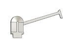
Last but certainly not least, the Rangefinder Stalk. There isn't much to say on this part. The Inner Ear model had already taken the thickness and diameter of the bottom of the Stalk into consideration so we just needed to ensure that the stem fit. The screen-used Stalks are pretty crudely machined and aren't symmetrical below the top like they have traditionally been replicated. If modeled accurately, the stalk should NOT sit perfectly at the 12'o'clock and you should see a small gap between the Stalk and top of the Inner Ear. Fit and function of the assembly was checked digitally with a custom model of the vintage UND Labs Microswitch. Lets go prototype.
Step 4 - Print, Scale, and Reprint the Upper Ear Assembly
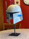
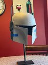
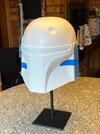
To ensure that the assembly works in the real world, we printed the Earcap, Inner Ear, and Stalk at full scale. Physical threads were imbedded into the models prior to printing so that we could use actual hardware we had on hand to complete the assembly. Luckily, we even had a metal Axle Screw that we were able to use to complete the assembly. Once assembled, everything functioned as well as we had hoped it would, and we moved straight into scaling. We already had the ideal scaling integer we needed from the Left and Lower-Right Ears, so there wasn't any work to do other than to make some within-tolerance adjustments to ensure function once scaled. The scaled models were exported, printed, and fit onto Gen 2 helmets for testing.
Pictured below: Some in-progress photos of the test fit process:
 -
- 
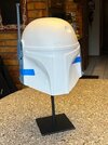
Without getting too far off topic, I just have to say that adding high-res 3D Printing to our prototyping toolset has been a real game changer. Having usable prototypes in hours or the next day has already saved us months of going back and forth with machine shops to get adjustments made. Truly I could not imagine where we would be in this particular project without this technology.
Step 5 - Production Preparations
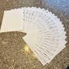
At this point, the hard work is done; The tedious work begins. Each model requires an individual technical drawing with dimensions, tolerances, material/finish specifications, and other various important callouts. These drawings get sent over to our machinists to review and provide us with a quote. Usually the drawing creation process is a pretty quick and painless. However, here is the breakdown of drawings for this project: 7 Parts Drawings, 10 Custom Hardware Drawings, 1 Custom Packaging Drawing. In total, over 18 pages of drawings. This process took time. Lots of time. After a first pass of all drawings, a second review pass was completed on paper over several days to ensure the drawings contained all needed specifications. The end is FINALLY in sight!
Step 6 - Machining Samples and Production
This is where we find ourselves at the time of this post. We received quotes back from our suppliers and have selected the shop we're ready to move forward with. The shop agreed to provide us with 3 production samples which will be produced over the coming weeks. We will validate those samples meet all specifications and, Force willing, we will greenlight production. Once production parts arrive, they will go through QC, sorting, bagging, and packaging before departing to some incredibly wonderful and patient folks.
Before closing post, I want to mention a couple things that we didn't get to yet.
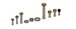
Custom Hardware - We have reverse engineered and modeled all of the hardware we have been able to verify is used on the screen-used helmets. Custom accurate hardware will be included with each kit to reflect what would have been on helmets at time of filming, and what is on them now. This includes the white nylon screw and brass nut seen on the Upper-Right Ear assembly of the ESB helmet. The nylon screw and brass nut were almost certainly added much later down the line as they are not a match to the period correct hardware the rest of the helmet uses. Both options will be included with all ears kits for customers to use whichever they prefer.
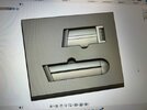
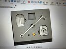
Custom Packaging - Packaging (and unpackaging) Ears in our previous runs was a horrible experience that took an enormous amount of time. To protect the kits both when shipping to us and on their way to our customers, we designed custom foam packaging to keep everything safe and sound. This will eliminate around 80% of the lag time between receiving production parts and when they get dropped off at the Post Office.
Pictured Below: 3D assembly of our custom foam packaging in CAD
If you made it this far into the post - Thank you! Hopefully this process has been enlightening or at least interesting to someone. This project has truly been a labor of love that we are really proud of so far. I'm dropping this in the "Boba Fett Helmet" section of the forum to hopefully preserve some of the information that typically gets lost when sales threads expire and get deleted. Also, this is not a sales thread.
More updates to come as we await the arrival of production samples! If you have any questions, I will be happy to try and answer them. Feedback welcomed.
Cheers!,
Dakota
P. S. We, myself, and I - Only since it has come up before.. If you're confused why "we" and "I" have been used alternatively in this post or elsewhere, this is for you. We, MachineCraft Replicas, are a company/brand comprised of myself, Dakota, and my wife, Holly. Now that most of our orders get processed through our web store, I realize that some of you don't or have never interacted with Holly, but she used to be the one to answer emails and process a majority of our orders. While she doesn't really interact with the community directly, she is a very large part of MachineCraft and helps with bagging, packaging, shipping, knurl counting, and much more to keep things ticking around here. When speaking on behalf of MachineCraft, I feel it would be disingenuous to not speak as a collective "We" given all that she does, even though she probably doesn't care either way. If you didn't know, now you know!
Hi everyone,
I have been anxious to write this post for some time. This is by and large the most complex and time-intensive project we have ever worked on - Definitive Metal Ears for Lineage Helmets.
Backstory:
In late 2021, we started working with new suppliers and gained access to significantly nicer quality parts at better prices - a huge win-win. We had completed our helmet run in 2020 and had run out of ears later that year, but even after the helmet runs we still received many requests for ears sets, including from studios working on The Mandalorian and The Book of Boba Fett. Now that we had access to better suppliers, we knew we could make even nicer ears for less than half of the cost of our original run, and we could pass those savings onto our customers - everybody wins.
The original plan was to use the same models as our original Helmet/Ears run. The raw models were designed by another member of this forum and then scaled and modified in-house for proper fitment on Gen 2+ helmets. These models were worlds better than anything to date as some measurements were taken directly from the real props. In early 2022 we pulled the original models into a CAD program we now use and started to discuss the project with a new production partner.
When we brought the original models back into the design space and started comparing to references, our production partner started pointing out several details that weren't captured in the original models. Some of these flaws are small, and some of them are difficult to be unseen once you know they exist. I was a little caught off guard - I didn't think the original models left much room for improvement. Nonetheless, we discussed further and decided to send the original models out for quotes to ballpark pricing so that we could open up pre-orders and gauge demand while developing an improved set of models using known measurements and reference photos. Our production partner took point on the redesign as he is incredibly talented and has great tools to work around lens distortion when modeling from photographs. Our projected ship date was June/July, 2022.
Improved Models:
In early June 2022, we received improved models for the Left and Lower-Right Ears. The models included features that were missing from the original models and were definitely a step in the right direction. We 3D printed the models with our high resolution SLA printer and things just didn't quite line up the way that we thought they would. Some dimensions lined up perfectly, and others were just off-the-mark. We came to the conclusion that the models we received were already scaled, so we printed them at full scale. Same story - dimensions that did not line up with the first prints were much closer, but the shift caused other things to drift off. This wasn't exactly new to us - we had a similar experience when scaling the original models from our helmet run.
With production well out of reach a week into June , we knew we had to bring in more hard data to use as a 'source of truth' to nail these parts. We got ahold of just that, and started comparing the improved models to the new data in hopes of making minor adjustments to take us right into production. We unfortunately had to part ways with our production partner after acquiring this data, and because the newer models weren't produced in the same CAD software we use, it was easier to just start over from scratch using the new reference.
Final Models:
Here we are - back at square one. I won't lie, this was a pretty low point for myself mentally. While we now had everything we need to produce the best ears possible, nothing up to this point had worked out the way it was supposed to, and we were now well past our projected delivery dates. A plan was developed and we started moving forward.
Step 1 - Model Singular-Interfacing Parts at Full Scale (Left and Lower-Right Ears)
We decided to start by modeling the Left Ear and Lower-Right Ear. Why? Two reasons.
Reason 1) Both of these pieces only directly interface with 1 other part; The Helmet. The less mechanical complexity, the better.
Reason 2) The Left Ear is the largest part of the entire kit that interfaces with the helmet. This also means it will be most affected by even small scaling adjustments. More on scaling later.
Accurately modeling parts you don't physically have in hand is challenging. I used to think that the more types of reference you have, the easier the modelling process becomes. The opposite is true. When working with caliper data, you have to identify which measurements can be relied on, and which to throw out. When working with photos, you have to account for off-axis angles and lens distrotion. When working with 3D data, you have to align mesh models to the planes that you're creating your models on, and/or then to the models themselves - VERY meticulous. Now combine all of these together and you have to create somewhat of tiering system for what data to rely on for whatever feature or dimension you are working on. On top of that, combining all of the data streams rarely leaves you with a nice 1-2 decimal point number, so there is a heavy amount of reverse engineering needed to uncover what dimensions are actually supposed to be.
Initial modeling was a slog for all of the reasons above. While working on the Lower-Right Ear I had a huge "Ah-HA!" moment that turned into developing a workflow I call the "Planes" method. This new method helped me extract really accurate measurements very quickly. I won't bore you with the details, but it was a game changer in this project. I worked through both models at a steady pace until they were complete, and then it was time to begin scaling.


Step 2 - Scaling the Left and Lower-Right Ears
Any time I mention scaling to accuracy-centric people in the community, it seems to be controversial. I totally get that we [collectively] want things to be exactly the same size as the original parts. Consider this: Lets pretend you had two painted Gen 2-3 helmets with say ~1.5% of shrinkage from the original prop; One you install 100% scale ears on, and the other you install ears scaled exactly to the amount of shrinkage the helmets themselves incurred. Now lets pretend that you have to pick these 2 helmets out of a lineup of 10 clones of the original prop. No one is going to pick out the helmet with the scaled ears - we simply cannot see that small of difference without the use of tools. The helmet with full scale ears with the left ear hanging way over the top and bottom of the left ear platform, however, would be easy to spot. All this to say - I promise, you do not want intentionally unscaled ears on an unintentionally scaled helmet.
To begin the scaling process, we started by 3D printing out the ears models at 100% scale using our high-resolution SLA printer. This printer has reliably produced prints for us with around .01-.02mm deviance from specified dimensions, which is remarkable. Once prints of the ears were cured, we affixed them to the helmet with some painters tape, approximated the needed scale, applied that scaling percentage to the full scale models, and began new prints. We repeated this process many times until we found the perfect fit, eventually implementing printd cylindrical studs on the back of both ears to simulate where the mounting hardware passes through the helmet. Now that we had our ideal scaling integer, it was time for the real fun to begin - the Upper-Right Ear assembly.
Pictured below: 3D prints of the many iterations we went through during scaling.

Step 3 - Model the Upper-Right Ear Assembly (And a discovery!)
"This is where the fun begins."
When modeling the Upper-Right Ear, you have several things working against you. The Earcap has to mate to the Inner Ear. The Microswitch has to fit in the pocket of the Inner Ear AND has to be properly placed for the Stalk to activate it in the down position. You cannot scale the Microswitch because it is a found part, but it's fit in the original prop is SO tight that making any modification can and will cause interferance. The Axle Screw has to pass through the Inner Ear, through the Stalk, and into the Earcap with such tight fit that it keeps tension on the Stalk without overtightening. The wiring exit from the Stalk needs to line up with the radius slot of the Inner Ear to allow wires to pass through and into the helmet from the Rangefinder. On top of all this, the assembly as a whole has to both look the part and clear the Lower-Right Ear if used on an ESB helmet. This assembly was a lot of work. It is also the part of the kit that is most different from our original "Hero Ears" run. I was never 100% satisfied with how this assembly fit the helmets on our original run, but chalked it up to the outright wonkiness of the ESB helmet; The real reason would actually be discovered next.
We started with the Earcap using the same methods we did on the previous pieces. To my surprise, the Earcap actually ended up being one of the smoothest pieces to model - until I got to the large feature on the bottom-center (Side Note: Do we have a name for this thing?). This feature was not lining up well, but everything else was, ruling out needing to align the part to the reference better. It was at that moment that I remembered a detail that boba87fett incorporated into their Elstree Precision ears, originally pointed out to him by Cantina Dude - the oddly rounded inside corner. After some studying the newer data and looking at reference photos, a discovery was made. The corner in question isn't rounded because of a broken or rounded end mill that was used to machine them, the corner is rounded because the right side of that bottom-center feature was HEAVILY filed down to clear the Lower-Right Ear! For ESB/SE Helmets, the bottom-center Earcap feature should NOT be centered and should be biased toward the left side if looking at the Earcap from the side of the helmet. This is specific to this particular helmet because the upper-right and lower-right ear platforms are not parallel to each other. If you want further evidence of this, look at well-lit reference photos that show the right side and bottom profiles of the bottom-center feature. There are very fine horizontal striations on the right side consistent with a fine file. These striations are not present on the left side. The angles this feature was filed to, and rounded corner has been near perfectly captured in our models and will be offered as an option for those who want it at no additional charge. Incorporating this modification makes it MUCH easier to get the Upper-Right Ear properly positioned without hitting the Lower-Right Ear. There you have it, something new for the die-hard accuracy crowd to enjoy.
The feature that was filed is inside of the green box in this photo, along with the file direction. It is not more obvious because it is filed down furthest on the right side of this image (closer to the helmet).

(If there is enough interest, I will try to produce a better representation of this in CAD)
With the Earcap modeled, we started modeling the Inner-Ear. This part was very heavy on reverse engineering work and took by far the longest to model. If you change any single dimension of the Inner Ear, it will affect function and/or fit of something else in the assembly. Many careful considerations were taken during the entire modeling process of this part to ensure that every piece fits like a glove. At this point that we began building an assembly and setting up cross-sections to check fitment between the Inner Ear, Earcap, Microswitch, and all of the accurate hardware we modeled earlier in the process (more on this later). On to the Stalk.
Last but certainly not least, the Rangefinder Stalk. There isn't much to say on this part. The Inner Ear model had already taken the thickness and diameter of the bottom of the Stalk into consideration so we just needed to ensure that the stem fit. The screen-used Stalks are pretty crudely machined and aren't symmetrical below the top like they have traditionally been replicated. If modeled accurately, the stalk should NOT sit perfectly at the 12'o'clock and you should see a small gap between the Stalk and top of the Inner Ear. Fit and function of the assembly was checked digitally with a custom model of the vintage UND Labs Microswitch. Lets go prototype.

Step 4 - Print, Scale, and Reprint the Upper Ear Assembly
To ensure that the assembly works in the real world, we printed the Earcap, Inner Ear, and Stalk at full scale. Physical threads were imbedded into the models prior to printing so that we could use actual hardware we had on hand to complete the assembly. Luckily, we even had a metal Axle Screw that we were able to use to complete the assembly. Once assembled, everything functioned as well as we had hoped it would, and we moved straight into scaling. We already had the ideal scaling integer we needed from the Left and Lower-Right Ears, so there wasn't any work to do other than to make some within-tolerance adjustments to ensure function once scaled. The scaled models were exported, printed, and fit onto Gen 2 helmets for testing.
Pictured below: Some in-progress photos of the test fit process:
 -
- 


Without getting too far off topic, I just have to say that adding high-res 3D Printing to our prototyping toolset has been a real game changer. Having usable prototypes in hours or the next day has already saved us months of going back and forth with machine shops to get adjustments made. Truly I could not imagine where we would be in this particular project without this technology.
Step 5 - Production Preparations
At this point, the hard work is done; The tedious work begins. Each model requires an individual technical drawing with dimensions, tolerances, material/finish specifications, and other various important callouts. These drawings get sent over to our machinists to review and provide us with a quote. Usually the drawing creation process is a pretty quick and painless. However, here is the breakdown of drawings for this project: 7 Parts Drawings, 10 Custom Hardware Drawings, 1 Custom Packaging Drawing. In total, over 18 pages of drawings. This process took time. Lots of time. After a first pass of all drawings, a second review pass was completed on paper over several days to ensure the drawings contained all needed specifications. The end is FINALLY in sight!

Step 6 - Machining Samples and Production
This is where we find ourselves at the time of this post. We received quotes back from our suppliers and have selected the shop we're ready to move forward with. The shop agreed to provide us with 3 production samples which will be produced over the coming weeks. We will validate those samples meet all specifications and, Force willing, we will greenlight production. Once production parts arrive, they will go through QC, sorting, bagging, and packaging before departing to some incredibly wonderful and patient folks.
Before closing post, I want to mention a couple things that we didn't get to yet.
Custom Hardware - We have reverse engineered and modeled all of the hardware we have been able to verify is used on the screen-used helmets. Custom accurate hardware will be included with each kit to reflect what would have been on helmets at time of filming, and what is on them now. This includes the white nylon screw and brass nut seen on the Upper-Right Ear assembly of the ESB helmet. The nylon screw and brass nut were almost certainly added much later down the line as they are not a match to the period correct hardware the rest of the helmet uses. Both options will be included with all ears kits for customers to use whichever they prefer.

Custom Packaging - Packaging (and unpackaging) Ears in our previous runs was a horrible experience that took an enormous amount of time. To protect the kits both when shipping to us and on their way to our customers, we designed custom foam packaging to keep everything safe and sound. This will eliminate around 80% of the lag time between receiving production parts and when they get dropped off at the Post Office.
Pictured Below: 3D assembly of our custom foam packaging in CAD


If you made it this far into the post - Thank you! Hopefully this process has been enlightening or at least interesting to someone. This project has truly been a labor of love that we are really proud of so far. I'm dropping this in the "Boba Fett Helmet" section of the forum to hopefully preserve some of the information that typically gets lost when sales threads expire and get deleted. Also, this is not a sales thread.
More updates to come as we await the arrival of production samples! If you have any questions, I will be happy to try and answer them. Feedback welcomed.
Cheers!,
Dakota
P. S. We, myself, and I - Only since it has come up before.. If you're confused why "we" and "I" have been used alternatively in this post or elsewhere, this is for you. We, MachineCraft Replicas, are a company/brand comprised of myself, Dakota, and my wife, Holly. Now that most of our orders get processed through our web store, I realize that some of you don't or have never interacted with Holly, but she used to be the one to answer emails and process a majority of our orders. While she doesn't really interact with the community directly, she is a very large part of MachineCraft and helps with bagging, packaging, shipping, knurl counting, and much more to keep things ticking around here. When speaking on behalf of MachineCraft, I feel it would be disingenuous to not speak as a collective "We" given all that she does, even though she probably doesn't care either way. If you didn't know, now you know!
Last edited:
