continued, post 2 of 3
5. National Semiconductor DM7400N integrated circuit (RS stock no. 305-490)
The wavy ’N’ logo is the logo of National Semiconductor (1959-2011). I think Fairchild Semiconductor did make some of the earliest ones after they were invented at Texas Instruments, but IC’s made by Fairchild have their ‘F’ logo as in the pic below:
History side note: IC designer and crazy genius
Bob Widlar left Fairchild in 1965 for National Semiconductor and made it into an IC superpower.
You can find vintage National Semiconductor 7400N’s on ebay without much difficulty. The appearance of the NS logo changed over time. The newer ones, mid 80’s and beyond, have a stripe on the left with a small wavy N. The older ones have an ’NS’ in a funky computer font which was in use as late as 1976. The era of 1977 to 1982 is the style we see on the original board.
Different logos and fonts for National Semiconductor over time:
The logo style as seen on the board is not hard to find. Finding 7400N’s with the 027P designation is a different story. That’s a lot harder. I’ll explain why in a moment.
After a very long tedious daily search, I did find DM7420N’s on ebay with the exact logo and font size as well as the 027P designation. The 7420N doesn’t work the same as the 7400N, but I bought some anyway just because the stamping looks so much like what’s on the helmet board. After such a long search, it was a thing of beauty to behold.
The closest I could get with a 7400N was a 007 batch code, which isn't too shabby. No sticker necessary really.
License to kill? Yes. Deadly. See below.
A Bitter Truth Revealed
Just when I thought I had become powerful with the force and had this part in the bag… after all that hunting and researching, I may have finally dug a little too deep. Because it turns out there is a bit of surprising news about that “027P” designation. I was curious about that code, so I looked into it… I wish I hadn’t. There is indeed bliss in ignorance, as they say.
and so comes the plot twist nobody saw coming…
It turns out ‘027P' holds some important information. It's a date code in the format YWW (YearWeekWeek) for the manufacturing date, which tells us when the IC was made (‘P’ is the plant ID). Each week had its own code, so this is why finding a specific code is tough. It has to be a chip made the same week at the same plant to have the same code. National used only the last digit of the calendar year until 1983 when they switched to a YYWW format. So for example, an IC with the code 837 would read ‘8’ as the year 1978, and 37 as the week of the year, so it would mean the IC was manufactured in 1978 week 37. It’s not an expiration date. IC’s don’t expire exactly (more on that
here). It’s a manufacturing date. Full explanation
here on how to read National Semiconductor date codes (probably from the early 2000’s).
another example: this National Semiconductor MM5782N has date code 620, which is 1976 week 20:
So our ‘027P’ batch code means it was manufactured the 27th week of year 0. Well, what’s year 0? The 0 stands for
1980.
We know the ‘0’ is 1980 not 1970 because the logo style confirms the era as post-1976 and pre-1983. I hear the gears grinding in your head right now. That’s right. This IC was manufactured and put on the board well after ESB had already hit theaters (ESB release date was May 21, 1980). I truly did not want to believe this. It had to be some kind of glitch. This could not be how to read the batch number.
For a couple of days I continued to believe that's not true, that's
impossible. But the more I looked into it, the more the evidence piled up confirming ‘027P’ did, in fact, mean it was made in mid 1980. The week of June 30 to be precise. There’s just no way around it: this chip was not on the board during the filming of ESB. How can this be? Why didn’t Ben tell us? I don’t know for sure but I have some ideas.
First, it sits in a socket, so it’s actually very easily removed and replaced. No soldering or rewiring is required. Second, perhaps there was a problem with the original IC so they changed and/or updated it. But why would they update it after filming? The only answer I can conceive of is it was done to prep for ROTJ when they still thought they would use the ESB helmet for Episode VI (new pet theory: maybe the guy who put in the 027P IC was the guy who dropped the helmet and gave it the giant left eye crack!).
So for this build, the 1979 filming helmet, the exact make for this part is actually unknown and may be lost to time. $#*%@! The original IC would’ve had a different batch code, different font size, too, or could’ve even been different make altogether. All I can do now is guess. And my guess is it’s either a RS-branded, National, or Texas Instruments 7400 from late ’77 or early ‘78. We know the ST had working electronics installed prior to June 28, 1978, so those are the most likely 7400 IC’s to be on the board by that time. I do have a Nov 1977 NS I can use unless I find an RS branded one, which might be the more likely chip.
But wait. There’s yet another plot twist (this is where you might need that box of kleenex). Remember the RS 7416 (#4 on our list here) which endeared us with its oversized logo and home-grown British charm? It has the same wretched secret hiding in plain site. It’s our own character flaw not to see through the deception sooner. It’s batch marked “8105S.”
That’s a YYWW date code. I’ll give you three guesses what that means. That’s right. Another surprise betrayal. That one was made the week of Jan 26 1981!
Monkey spit! How can I make a faithful duplicate of the 1979 board if the two main components were swapped after filming, leaving no record of what they were? I don’t know. Maybe the search for the exact IC’s was for naught. A complete waste of time. Thanks National Semiconductor… you and your namby-pamby date codes.
Real ad for National Semiconductor. Clearly the villain:
One thing we must consider in light of this information: there is a possibility,
however unlikely, this entire board was fabricated after ESB was released. It’s possible the original one which was used for ST and the ESB hero during filming was discarded and replaced by this one.
(last animated gif, promise)
There are, as yet, no other components on the board I can ID as being strictly post-1979 in origin, so let’s just banish the thought. The consequences are too terrible to contemplate.
And it's pretty unlikely. > (
*update: this may actually be the case after all: evidence here. summary: the board itself looks to be dated mid-1981. All the date codes found on the board here)
Whatever the case, there is certainly a mystery here. An untold story. I think it lends solid evidence that the ESB hero was originally intended to be used for ROTJ early on. The damage to the helmet is probably why they changed course. And now we can probably pin down the timeline of the damage to after the IC swap but before the ROTJ stunt helmets were made. Which would put the date of the damage no earlier than Feb 1981, but probably some weeks later than that at minimum since it has to go from the plant to the warehouse and be added to stock before purchase and delivery. I don’t think we have a date yet for when the stunts were made.
Ultimately, the true tale of the IC switcheroo will have to be for another time, by someone who knows what happened. Probably that guy who dropped the helmet.
I understand there might be those who don’t want to accept this conclusion. I don’t blame you. I prefer delusions to reality, too, in some cases.
Caveat:
I acknowledge that the interpretation of old date codes rests on assumptions that are hard to verify beyond doubt, namely that the codes present on these specific chips are in fact the common YWW and YYWW formats. There are other formats and some plants simply did the formatting wrong from time to time. To clarify this mystery will require some solid evidence. One possible place this could be found is on period data sheets from RS Components and National Semiconductor for these series chips. They *should* mention the dating convention used for the product at that time. The earliest data sheets I've been able to find so far are 1989 for National and nothing for RS. I'm more than happy if we can find information that proves I got it wrong.
I did reach out to someone who is very knowledgeable on date codes just to see if I am totally off-base with my interpretation. I will see if he will let me mention him or if he wants to join the discussion, but here is what he had to say regarding the mystery:
Personally it seems unlikely that those are the original chips, as the date codes look to be completely straightforward, and indeed newer than the film. (Good film, too! My least favourite as a kid, and then my favourite as I got older.)
Seems like a pretty smart guy if you ask me. He certainly understands ESB's proper place in the Star Wars saga (as an adult at least). For now, I suppose staying with a period correct 7416 and 7400 will do since no one can ever know if it’s accurate or not, which is a reality that stings after so much research. Or there is the possibility the 7416 could’ve originally been a 7406 before it was replaced, since that’s nearly the same. If anyone wants to make the post-ESB board as pictured, there’s no shame in it. I guess. Heck, I’ll probably make one for my SE helmet. If anyone wants a 7420N 027P from mid 19freakin80, just PM me. I have a few. I’ll be glad to get rid of the stinkin’ rotten backstabbing wretches.
on my boards:
The June/July 1980 chip, post-ESB (for a non-functional SE board)
A November 1977 that could've been on the board by June 1978 (for the functioning 1979 hero helmet)
6. Unknown make tantalum bead capacitor of unknown specs, ??µF / 6.3 volts (RS stock no. 102-730?)
As if the treachery of the IC’s wasn’t enough, there is no time to recover before we must now come up against an actual unknown. These blue tantalum capacitors were the one component I have still not been able to ID a maker for. If anybody has ideas, please speak up. I suspect they are from West Germany (anybody remember that country?), but that’s just a hunch based on the use of the comma instead of the period on the ‘6,3v’ on component #7 below.
It’s hard to know the exact specs just by the top-down outline, so we are left to guess yet again. But let’s make an educated guess based on what we know from #7 on the list below. The working voltage is probably the same, 6.3v, since the battery pack is 6 volts. But it looks beefier so the capacitance is probably higher. Exactly what, I don’t know yet, but it’s definitely higher than 47uF. Maybe double. A 100uF, if that’s it (just a guess), is stock no.102-730. I’ll have to wait until I test the design in phase 2 to see what works, unless someone with knowledge of the original part wants to let us in on the secret.
When sourcing vintage parts like these sometimes you just have to go for broke and buy giant piles of the stuff to find what you’re looking for. Most of the time sellers won’t pick through them for you. They’re lazy. Ah, you already know this. Ebay 101 stuff. You got it.
If anybody wants to do a non-functioning cosmetic board, there’s plenty of stand-ins in this lot from Germany that’ll play the role of part #6 and #7. PM me if interested. I don’t think I will ever run out.
on my board:
7. Unknown make tantalum bead capacitor 47µF / 6.3 volts (RS stock no. 101-844)
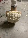
Finally. An honest character. No guessing needed here. It’s really tough to find these exact values in blue bead capacitors like this. Like I mentioned with the previous one, I suspect these were probably made in West Germany, so you might want to brush up on your Deutsch and search ebay DE (tantal, perle, kondensator, elektrolytkondensatoren, elko), although on rare occasions you will see RS packaged tantalums pop up in the usual spots on ebay though I’ve not yet seen blue ones. Word on the street is these old blue capacitors are trouble, especially in the low voltage range such as this. They’re unreliable and like to go out in a blaze of glory. Sounds like potentially good times. This will warrant further discussion in part 2 (here’s an informative paper on the broader problem of all tantalum capacitors
here). Remember kids, always wear your bonnet!
If the blues give me trouble, I have new stock yellows ready to fill in.
on my board:
8. Neohm 0.5w thick film resistors 3.3kΩ ±2% (RS stock no. 145-311)
And as we come to the final component on the board, we enter the land of the unicorns. At first glance these look like normal 1/4w 3.3k ohms (aka 3300, or 3k3) molded carbon film resistors made by Allen-Bradley or similar. But look closely at those stripes. The fourth stripe (from left) is red… and that’s what makes this a unicorn. That’s the mark of ±2% tolerance. It turns out RS components didn’t have carbon film at 2% at the time. Only 5% tolerance was available (RS stock no. 131-312). It also turns out 2% carbon resistors were not common in the UK at all in this period. The ’79 catalog did have metal oxide resistors at 2% (pic below). They were 1/2w and the dog-bone shape with blue/gray body color. Possibly made by Electrosil. But obviously those aren’t the ones.
Vintage RS Components 2% metal oxide had a blue/gray body color:
But RS did have another 2% resistor at the time: 1/2w thick film resistors. They are the right size at 6.5x2.4mm and the right shape with a molded case, and look the part. They were made in Italy by Neohm (oh boy, many, many Bothans died to bring us this last piece of information).
The reason I say we are in the land of unicorns is because well, the obvious: they’re really tough to find. After searching long and hard it became clear that finding a pair of these was not going to be easy. In fact, I was preparing alternatives because it began looking highly unlikely that I would ever find any before my children left for college (they’re in 2nd grade currently).
Unicorn sightings in Bath
But then… the clouds parted to let the light of the Force shine upon my sad little 1979 vintage replica board, its heart ripped out by IC date coding practices, etc. I came across an auction of old electronics parts in three large cabinets in Bath, England. In a couple of pictures, random bins were slid open to show their contents. One of the few open bins happened to be 3.3k resistors, and in the jumble of different makes and power ratings were four, possibly five thick films with the glorious fourth red stripe. What?! I immediately copied the photo and blew it up super large so my bloodshot eyes could see clearly through my tears of joy. I sat in stunned silence for, I like to say 30 seconds before I sent the picture to a friend to get a second opinion. Was I seeing things? It didn’t even matter. I was going to bid no matter what. And bid I did, using my ‘secret’ Star Wars number, a random number that comes up more than once in the OT. And won the entire lot. For five tiny resistors.
And it got better. What I thought was four, maybe five of them, turned out to be seven. Then I got lucky again — the seller was very pleasant and kind and sent me just the unicorns, charged me only a small amount for them and put the rest of the lot back up on ebay.
And that’s how easy it is to find these suckers. No sweat.
Let’s play ‘Spot the Unicorn.’ Can you find the 3.3k ±2% resistors in this lot?
Look closer
ah yes, there they are. Good job!
On the other hand, 3.3k carbon composite/film resistors at ±5% and ±10% are plentiful. Several manufacturers made molded carbon resistors with this same look, Allen-Bradley, Stackpole, Morganite, Ohmite, Vitrohm, TRW, Arcol, and on and on, and yes, even Neohm made these, too. I spent a long time down this rabbit hole before discovering the thick film resistors. If the 2% Neohm thick film is a unicorn, then these 5 and 10% carbons are horses. They’re ubiquitous and look the same except for one small but critical detail — the final red stripe.
Fourth stripe in gold means 5% tolerance, silver is 10%
The last two pics are carbon resistors made by Neohm for RS. You can see how similar they are to the thick film resistors on the original board. I want to emphasize these carbon types because they’re so cheap and easy to get, therefore they make an excellent replacement. The 1/4w would be the size you want. Just paint the fourth stripe red and you’re set.
Neohm 1/2w 3.3k ±5% carbon film resistors:
They should work electrically the same as thick film resistors, assuming the 2% tolerance is not really necessary (edit: turns out it's not).
For now, my fingers are crossed the unicorns I acquired will do what they were meant to do. I tested them and they were all performing rock solid at 1% or less which is perfect.
on my board:
At last, we are at the end of the journey and I have my happy ending. I ride off into the sunset on my unicorn(s).
[music swells to an emotional climax]
And thankfully that’s it for the components on the board. Here’s an easy shopping list for those of you who made it through all that. Congrats. If you skipped right over and came straight to this, you’re cheating. You should really take a moment to consider your lack of moral character:
1. Miniature p.c.b. ‘slide’ switch SPDT, made in France by APEM (RS stock no. 339-673)
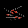
2. Silicon rectifier diode, 1N400X series, probably 1N4001 (RS stock no. 261-148)
3. Piher 0.5w high stability carbon film resistors 10Ω ±5% (RS stock no. 132-012)
4. RS branded 7416 integrated circuit, dated 1981 (RS stock no. 306-364)
5. National Semiconductor DM7400N integrated circuit, dated 1980 (RS stock no. 305-490)
6. Tantalum bead capacitor of unknown specs, ??µF / 6.3 volts (maybe RS stock no. 102-730?)
7. Tantalum bead capacitor 47µF / 6.3 volts (RS stock no. 101-844)
8. Neohm 0.5w thick film resistors 3.3kΩ ±2% (RS stock no. 145-311)
The RS stock numbers listed are vintage and some are discontinued.
Next post will finish part 1...
")