Chest display project

I'm not nearly smart enough to contribute to the electronics design part of this. But, one thing I've always wanted as a costumer was for the portion of the display in the chest to be very minimal. Just a small board with the LEDs on it. Then have a cable that runs down to, say, the belt pouches, where the main board would be. Then the board could be in a project box, rather than just loose.

I've had chest lights get damaged by sweat, plus I always welcome smaller components in the suit.

I forget who made mine, but it's 2 boards connected by a ribbon cable. Not exactly my dream setup, but close :)

Love that idea Brian!

Maurice..this is coming along nicely! (y)
 
Last edited by a moderator:
I'm fairly new to these boards and I have been following this thread with great interest. I don't want to step on any toes, but I'm not so sure that the assessment of the digit displays being the mitered version is correct. I have taken the comparison image from above, and enhanced it in photoshop. By tweaking the contrast on the actual chest lights to reduce the "glare" around the digits, and then tweaking the mitered example with some blur and over saturation, the difference seems fairly evident. The actual digits look more "rounded" (especially at the bottom; imho, due to the separation of the bottom bar from the lower left and right bars) while the mitered digits have a more "squared" look.

See enhanced image:
Chest Display Character enhanced.jpg

Jeff.
 
You know, I'm not really sure either way now. Spent some time in the gallery looking around and just couldn't find anything with a clear shot of the display. None of the close-ups showed the lights on. How about that Star Wars display going on in LA right now? Do they have a Fett suit on display? Maybe someone can get a good flash picture close-up of the display. Even if it's not on, it may show up with a good flash.

Doesn't really hold things up although I will definitely look around a bit more and see what's available. I think it's pretty much squared off or the mitered edges though. They don't get too fancy with the smaller ones. It is a little confusing too because some of them I looked at didn't really specify and the website photo would show one thing and the data sheet another. One thing that I caught was that the Avago one mentions an "industry standard pinout" which means there's a good chance that we could leave the digit style up to the builder. The square ones from Jameco are different pinouts though so I'll try not to design to that. I'm getting some of those just to prototype with since their only a dollar each but I won't do the board to that pinout.

We can figure this out though and I really appreciate the input. It's already making this much better than if I'd went off and done it by myself.

Stormtrooperguy, I'm glad you mentioned that because I was thinking about making an option to breakup the display from control board. What I'd like to do is draw the board out so that the leads that go to the display have a set of parallel pads along the trace so that if you wanted to separate them, you just drill those pads then cut the board right between them and run the wire between them. Thinking about the same thing for the onboard battery. Don't want it? Just cut it off!

The drawback to splitting the display from the control board is the number of wires. For the simple circuit, there would be about 9 wires between them. With this RWS one I'm working on, it's looking like 18 wires! I was kind of wondering how a ribbon cable would work. Seems like it might be hard to make certain turns. Where do you have your battery and the control board right now? I was thinking it could be in one of the pouches at the belt.

I was looking at the wiring that's offered and they start getting pretty think. If I was going to do 18 wires, I think I'd split them up into 3 or 4 smaller cables strapped together. Either way though, what I'd like to do is maybe orient those pads along the leads in such a way that they would fit a mounted ribbon cable connector. That way, if someone wanted to use one, they could or if you wanted to use wire, you could do that too.

I've got these little tabs on order that I figure can be an optional power setup that will allow for removable power leads. Planning to bend the leads and have them run off one side of the board. If you don't want them, just run the wire right to the holes rather than mounting them.

853927.jpg


For the micro display on my kid's costume, I have one of these on order and will just cut it and attach the short end to the jet pack's batteries and run the other end to the display.

2099139.jpg


OK, off to circuit drawing land...
 
I'm fairly new to these boards and I have been following this thread with great interest. I don't want to step on any toes, but I'm not so sure that the assessment of the digit displays being the mitered version is correct. I have taken the comparison image from above, and enhanced it in photoshop. By tweaking the contrast on the actual chest lights to reduce the "glare" around the digits, and then tweaking the mitered example with some blur and over saturation, the difference seems fairly evident. The actual digits look more "rounded" (especially at the bottom; imho, due to the separation of the bottom bar from the lower left and right bars) while the mitered digits have a more "squared" look.

See enhanced image:
View attachment 57483

Jeff.

I never said this is 100% the good version:

The digital characters used are this type (with approximation) and not the squared type used by others:

View attachment 57450

The idea is that they used that style (with a slight tilt to the right) or maybe this (missing tilt, but might be the correct one), at least in ESB

ESB Digit.jpg

While (if we can trust the exibition images) in ROTJ they used characters with squared ends:

ROTJ Chest Display.jpg ROTJ Srunt Chest Display.jpg

The first image is from the MoM exibit with the ROTJ Hero chest plate (this is a repainted ESB Promo #1 armor part), while the second image is a ROTJ Stunt(?) chest plate from the C-IV exibit (wich is the repainted ESB Hero armor part and it seems they changed the chest display too).
 
Last edited by a moderator:
My battery is in the pouch. There is a long lead that runs from the battery to the first board. That's where the bulk of the electronics live. Then a ribbon cable connects to the second board which has the LEDs and some of the resistors.

I'd offer to post pics, but my suit is packed away in the attic and I know I won't get around to it ;)
 
I did a deeper research on the chest display from the Empire and I found the 7th sequence and a new (and I hope) better time period between each sequence.

Chest Display Sequence Mine.jpg Chest Display Sequence New.gif

But I will start a new thread with all the new info.
 
Oh man, I just got the first one on the breadboard. It's a mess but it works. That's a more interesting sequence so I'll see how much more it would take to do it. The first one works pretty well with the 4 added logic chips. It's a 7 step sequence which works pretty well since at most you have 3 inputs to the gates which are easily available and fit 3 to a chip. The new one you have is really 9 steps considering the pauses at the blanked steps.


DSC01374.jpg


I had started doing the circuit board design but am not finding what I expected with the displays. There doesn't seem to be a choice of display styles with the same pinouts. I may have to make two different board designs. I started with the Avago 10 pins ones with the mitered corners but what I have on the breadboard are the 14 pin ones with the square corners. Since there's at least some evidence of the square pinned ones and since I already have them here, I'm inclined to design for them. The ones you have in the closeup sure look like the square ones I have - even 2 decimal points. And, if they're making this stuff in the SF bay area, I wouldn't be surprised if they are actually getting them from the same place I am. Jameco is the long-time electronics parts supplier in the bay area.

The circuit is getting pretty tight space-wise. I'm trying to make it fit on the 3" x 4" board but it might not work with more chips and the battery. There is also a power issue running all the 4 LEDs and some of the segments on the last display which are powered right off the 4017. So, I need to get some transistors.
 
Just go with whatever display you have. You've done an excellent job so far and keep it coming! Remember that the original chest plate has a concave shape and there's enough room to fit all the electronics. The same goes to the abdominal plate where they inserted a speaker:

Boba-Fett-Costume-MoM-121601A-376.jpg
 
Got a few things done on this.

  1. Worked out the power issues with the added LEDs in the bar display. Added 5 transistors and 10 resistors.
  2. Worked out the logic gates for the longer sequence and got it to work with the same number of chips. Just 3 more resistors added. Have the parts ordered and should have them tomorrow.
  3. Re-did the micro display board with the simple circuit adding the battery and switch. I'd like to get this one written up just to get it off the todo list.
  4. Installed the micro display in my kid's costume. Don't have a lens for it yet though. Any tips on where to get a thin plastic lens? I seem to recall some filing tabs that had little inserts that might be just big enough for the little slots I have. They are only like 1" wide.

Stormtrooperguy, I just ran into a 2007 post where you showed your chest display and I was surprised that the ribbon cable goes sideways. So I assume you run the cable through holes under the vest. I was thinking to make the board with a saw point and extra tabs but with the leads running downwards so the control board would be in a pouch or something with the battery pack. It would take about 15 wires between boards for this more complicated circuit. I don't really like the limitation on what direction you can take a ribbon cable so I'm thinking about other options. The control board is going to be a bit bigger than these since I'll be using 5 14 pin chips and 1 8 pin.

ledfront.jpg


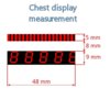
Based on the armor out there, what would the best spacing be for the LEDs? Tk409 lists these measurements:

  • Length of slots: 43mm
  • Height of top slot: 4mm
  • Distance between slots: 8mm
  • Height of bottom slot: 8mm

The width of the displays and LED bars I have are going to be 50mm wide. Although the original suit seems to cut a little off the display so the actual holes may want to be a little shy of that 50mm. I'll set the distance from top edge of the 7 segment display numeral to the bottom edge of the LEDs in the bar at 8mm. If there is a better spacing, just let me know and I can tweak it.
 
I did my display sequence by replicating the led positions on both slots using images (mainly the ESB stills) from the Gallery. Here are my measurements of the display slots, which is close to TK409's list:

Chest Display.jpg
 
Thanks Jeff. It helps a lot that all you guys know the real specific and resources on this stuff. I've been grinding away at the circuit board design and just today said "uncle" on trying to get it to fit on a 3" x 4". It's looking more like a 3.5" x 4.5". But hey, only partial defeat right? I'm sure that we can get that later sequence going but the board size may make it less likely to be something you'd want to keep on one board. It'll be designed with either option in mind though.

Rafalfett, those measurements will workout perfectly. Thanks for posting.
 
OK, holidays are done - back to work on this. Been working on the board layout for the full sized version and that's been tricky. Lots of jumper wires! Almost done though. Haven't put it on the proto board yet. Decided I wanted to do the write-up on the micro board just to get one thing off the list. Hopefully this is a good enough explanation.

Boba Fett Chest Display

Just let me know if there is anything I should change here. Also wondering if I should import the whole thing here once it's all done just so it's searchable here. Anyway, back at it. I'll try to get the prototype up on the board this week.
 
This is all mind-blowing! I tried making one off of a diagram from someone, but it was not drawn so well. They had left out necessary resistors and such. I have been researching but I still have trouble understanding some stuff on how to scratchbuild. I can read layouts so if there is a definite layout/diagram, does anyone know where it is?
 
This is all mind-blowing! I tried making one off of a diagram from someone, but it was not drawn so well. They had left out necessary resistors and such. I have been researching but I still have trouble understanding some stuff on how to scratchbuild. I can read layouts so if there is a definite layout/diagram, does anyone know where it is?

Mauricemeyer has his own site where (among other useful things) he posted the chest display diagram too. Here is the link to the site ==> Maurice Meyer's Home Page - Boba Fett Chest Display
 
This thread is more than 10 years old.

Your message may be considered spam for the following reasons:

  1. This thread hasn't been active in some time. A new post in this thread might not contribute constructively to this discussion after so long.
If you wish to reply despite these issues, check the box below before replying.
Be aware that malicious compliance may result in more severe penalties.
Back
Top